 Be forwarned: the following modification will void your warranty! Don't say I didn't warn you...
 When I first acquired my GVTPGIIP, I was disappointed to learn that it would not work on my Centris/Quadra 650 because of the lack of a new-style serial port, or Geoport. The GVTPGIIP requires the Geoport, as it supplies +5VDC through a new ninth pin. Devices that are designed for the Geoport have a DB-9 connector to plug into one of the Mac serial ports. As the old serial ports use DB-8 connectors, I needed to find a way to make it work.
After some tinkering, I was able to add some components to the modem that allow it to use an external power supply. I also "reverse engineered" the DB-9 to a DB-8.
 Be forwarned: the following modification will void your warranty! Don't say I didn't warn you...

Inside: The Power Supply Situation
Inspect the rear of the modem. You will see a cable coming out of the modem, two telephone plugs to the right of the cable, and two rectangular filler plates to the left of the cable. Those two rectangular plates led me to believe that this modem might not be all that different from a Teleport Gold II. Opening up the modem, I discovered that the "motherboard" had solder pads on it for a switch and a voltage regulator. I decided to add both of these. After probing and testing the modem while it was attached to a 6115CD, I learned enough to make the changes. After collecting the parts and my wits, I went to work, and presto! It came to life. How did I do it, you ask. Read on.
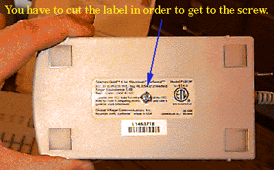
To open the modem, you must pierce or remove the FCC ID sticker on the bottom of the modem. There is a single screw that holds the modem together. Remove it and carefully lift off the cover.
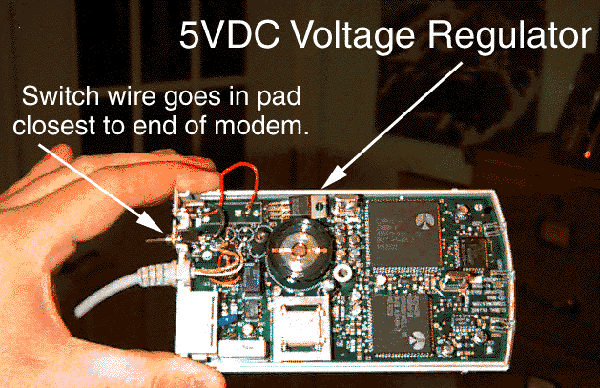
You will see the modem's "motherboard." It has many components, but the parts of interest are in fact the parts that are missing. Global Village was kind enough to put soldered pads for the missing parts, so putting the voltage regulator in is a snap. For convenience, I also added a switch and a removable plug from the transformer to make it more portable. I used a 9V DC power supply from an old tape player. This is basically a transformer that plugs directly into the wall and has a wire that comes off and plugs into the tape player. There are hundreds of variations on this theme. You could even use a 9V battery, but I do not know how long that would last. I cut off the old plug and attached a new one.
If you plan to attach a switch, do it first. It'll save you headache later. Do not plug in the transformer into the wall until the very end! If you try to power up the modem without the voltage regulator in, you may do some damage. Although you may want to experiment, here's the procedure to duplicate what I did:
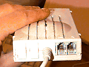 | 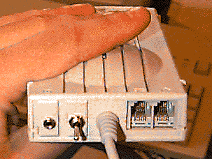 |
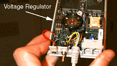
Find a switch which has a threaded neck for panel mounting. I got a subminiature SPST toggle from Radio Shack. The diameter of the hole that must be drilled is perfect for the space we have. Drill the appropriate diameter hole in the rectangular filler plate. It should be in the panel right behind the pads labeled J2 on the motherboard. Mount the switch to the filler plate. Solder a short wire from the pad closest to the back of the modem to one side of the switch. If you want to have a removable power supply, you will need to make a male plug and female socket and attach the socket to the remaining panel of the filler plate. Pay careful attention to polarity! Failure to do so will result in the loss of your modem! I chose a subminiature jack and socket from Radio Shack, since they come in pairs and fit nicely into the filler plate. Whether or not you put in a power supply plug, you will need to drill a hole in the filler plate for the wire from the power supply.
Attach the remaining side of the switch to the negative wire from your power supply. I'll say that again. Attach the other side of the switch to the negative wire from your power supply. Now, attach the positive wire from your power supply to the pad second from the top in the space labeled SW1 on the motherboard. Now we're ready for the voltage regulator.
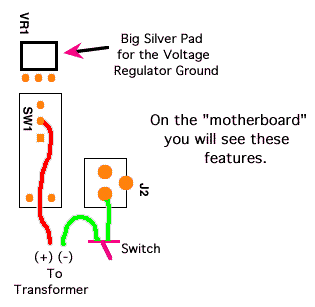
I used a Motorola MC7805CT 5Volt DC regulator, which I got from a local electronics supply store since Radio Shack was out of them. It fits right onto the board as if made for it. Not a big surprise, really. See the pictures below for its orientation. Soldering is a bit of a trick, as the holes are already filled with solder. If you have a solder sucker, suck out the old solder, push the regulator into the holes, then re-solder. If you do not have a solder sucker or solder wick, heat each hole and slowly work the regulator into the hot solder. Do yourself a favor and get a solder sucker.
After you get the regulator soldered onto the board, bend it over as shown below so that the cover will close. Put the filler plate back in and close the cover. Screw in the screw and the power supply problem is solved.

| At first, I thought about buying a DB-8 connector at my local electronics supply store, cutting off the DB-9, and soldering on the DB-8. Then I looked at the connector more closely. The only differences between a DB-8 and a DB-9 is that there is one more pin and that the DB-9 has an indentation along the top of the metal shield that wraps around the pins. Clearly, if I were to remove the extra pin and bend out the indentation, it would work, right? Grabbing a pair of small needle nosed pliers, I carefully ripped out the extra pin and straightened out the indentation. The extra pin is the third one from the left in the second row when you are holding the modem cable with the flat end up. Voila! From a DB-9 comes a fully functional DB-8. Nevertheless, if you elect this course of action, be very careful not to bend any of the other pins, either while removing the extra one or while bending out the indentation in the shield. If you do bend any of the adjacent pins, be sure to straighten them out before you try to plug the modified modem into your computer. Here's a look at the modified connector: |  |
Now you are ready to give it a go. You do not need to have any global village software installed to use this modem. It responds to the AT command set with or without the Teleport Serial, Global Village Toolbox and GlobalFax software installed. If you do not need the FAX part, get rid of the Global Village software, as it (at least for me) causes more problems than it solves. The following configuration string enables 19,200 data rate, making this a pretty nifty modem for the money.
ATE0Q0V1X4W0N1
This one enables hardware handshaking.
AT&F1&K3&D2
Good luck with this, and let me know how it goes. I am James Lockman and I can be reached at Lockjaw8y9@aya.yale.edu.